Starting by the obvious, what is a voxel ? A voxel is a short for volume element in the same way as pixel is a contraction of picture element. OK that doesn't really make sense but they just wanted to make it sound the same. There are different kind of voxels, one that we won't consider here is to see voxel as a way to represent volumetric object as three dimensional bitmaps instead of vectors (by opposition, polygonal objects are made of vectors). In this situation voxels are like legos. Small bricks that constitute a bigger object, similar to the relation pixels have with the bigger image.
But here we'll only discuss the voxel terrain as featured in games like Outcast or Comanche. The voxel terrain engine is a 2.5D engine, it doesn't have all the levels of freedom that a regular 3D engine offers. It has the same degree of freedom as ray casting engines (popularized by Doom) and they are so close than in fact you could probably implement a voxel terrain engine as a ray caster. We won't do that, instead we'll use rasterization with a few tricks. Why is it called voxel if this isn't the same as the first definition ? Because our terrain is constituted by small 2D bricks that expand vertically. So this is a voxel, only a more restrictive definition of a voxel.
Introduction
This project was started as I discovered the screenshots of Outcast in 1999 and decided to do something similar. This was a rather large project given that I didn't know anything about 3D engines or C++, but the math seemed easy enough. What is following is the newest version using Win32 for the interface (sorry if I use a lot of Win32 notations but I guess that the algorithms explained below are portable enough).
For some laughs, the original versions with a bad case of programmer art (and an underpowered Pentium).
Why would you need a voxel engine nowadays ? Short answer you don't need one. If you've got a 3D accelerator you can have a very detailed terrain with multi texturing, occlusion with a z buffer, powerful shading languages, and most of the work (clipping, rasterization, transformation etc..) is done for you and is the fastest you could ever hope to get. You should see what follows as a mere exercise of fun. There are better tools, so use them.
Now that the disclaimer is on, let's go have some fun.
First there was the height map
The easiest and fastest way to represent a random terrain is through a height map. This implicitly associates a 2D coordinates with a fixed elevation. We obviously cannot represent all kind of terrains like that, there is no way we can have a arch or anything that breaks the rule "one height per position on the map". If you need something like that you probably don't want a voxel engine to represent your world. You don't need to read what follows, go look for polygonal engine (and probably 3D acceleration).

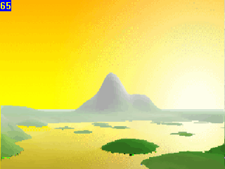
Utah
is too
complicated for our voxel engine. (all photos and images ©
Grégory
Massal)
The authoring can be tricky, there are real worlds data available as elevation maps, but what if I want to represent something that doesn't exist anywhere else ? Asking an artist to do a simple terrain with faults, mountains, crevices, plains, can be a lot of pain. There are tools that help you author random generated height maps. For this article I used the free versions of World machine and Terragen. And with some amount of work or by using pregenerated scripts you can get realistic enough terrains (go see their galleries for more).
For each position on the map I have a corresponding height encoded as a 8 bit number. 0 to 255 might not be enough for what you envision but you can of course vary the elevation range that is contained in those 8 bits (compression), and if that is not enough you can go for 16 bit integers or 32 bit floating point numbers. It's really a decision depending of your data and there are way to compress those bits better to achieve a similar result with a smaller memory footprint. I won't detail them too much. Let's go back to our design.
Make sure that the map you've created is using the full range of 0 to 255, this is small enough that you don't want to lose precious bits of information in the process. For this engine purpose I also had to make the map tileable. That means that if I go beyond the left side of the map, I can magically wrap to the right side of the map and not fall a cliff because the aspect of the right border is a perfect fit for the left border. I won't detail that too much, but there are ways to make sure of that, one is taking an untileable map and transform it into a copy of the same map duplicated four time and mirrored horizontally or vertically. This way the left border is perfectly equal to the right border. Inconvenient is that you have a map that is highly redundant (well you were going to make it tiled anyway..). Another solution is to generate a slightly larger version of the map, to crop the upper border and report the deleted bit to the lower part of the image with a smooth blend with the underlying image. That way the lower border will be a match with the upper border and this will look seamless enough. In this example I did this manually and this is far from perfect but with a bit of practice you'll have to be looking closely for defects. There are also advanced algorithms that try to preserve the features of the original image and minimize the repetition artifacts but that's too overkill for this little project.
Second there was the visibility
Before drawing every single terrain element you have to determine what is visible and what is not. This is both a performance and a correctness problem. If a terrain element is partially visible or totally occluded and you draw it anyway, then you have a correctness issue. If you draw terrain elements that are situated behind your camera or outside of your view then you have spent numerous cpu cycles for basically nothing.
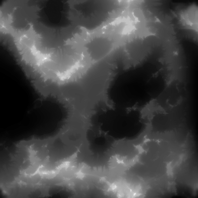
The above image represents what you can actually see from a given point of view (in red), most of the black areas are outside of the screen, and some parts that should be on the screen inside the view frustum are in fact occluded by terrain features in front of them. I cannot realistically go through every terrain element surrounding the camera and determine if they are clipped outside of the frustum, I will use a hierarchical representation with a coarse level and a detailed level, I will consider going through the detailed clipping only if the coarse has determined visibility or ambiguity.
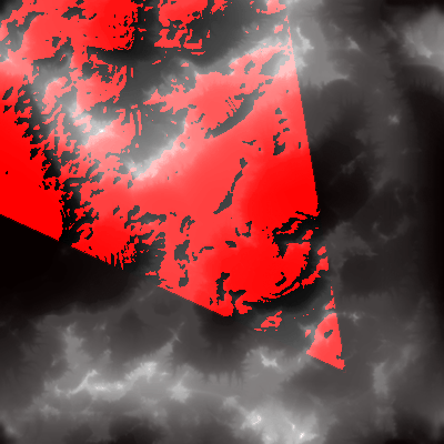
I'll only use two levels in my hierarchy, so deciding where to put the coarse level is strategic what is detailed enough to avoid unnecessary clipping work at the lower level (limit the ambiguity cases), and what is high level enough to not do unnecessary work at the coarse level. I've decided to go for 256x256 zones of terrain that can be quickly culled.
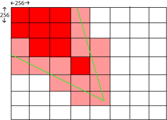
In pure red, you have zones that lies 100% within the frustum (the frustum, is the cone, or the zone delimited by those two lines in green that limit what we can potentially see in this world at a given rotation and position). In pink are those zones that are not entirely inside the frustum but that we have to include anyway because *some of it* is visible. In the worst case scenario that means that one terrain element can be visible out of those 65536. That's bad but we have to do with it or else go for a coarser grid.
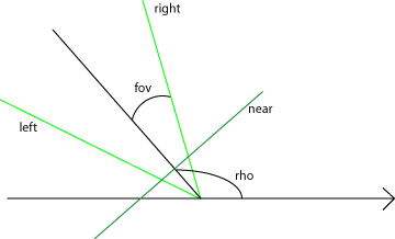
Clipping is a pretty straightforward operation, you have to test each angle of a quadrangle that delimits a zone against three lines that I call left, right and near. I put near at a short distance of the camera position, because I'll have to divide later by Z, the distance along the view axis and I want to avoid to divide by zero. Note that the farther we push near, the better performance we get but then we increase the risk of causing artifacts.
In order to clip, you have to determine the equation of each of those lines, finding the equation is equivalent to searching the normals to the lines in the 2D plane, the normals are defined in terms of fov and rho, the two relevant angles of this configuration.


So if we posed x1, y1, x2, y2 the four coordinates that define an axis aligned bounding box. Then we have the following code to clip against the near plane :
    dist1 = m_nearplane.a * x1 + m_nearplane.b * y1 + m_nearplane.c;
    dist2 = m_nearplane.a * x2 + m_nearplane.b * y1 + m_nearplane.c;
    dist3 = m_nearplane.a * x2 + m_nearplane.b * y2 + m_nearplane.c;
    dist4 = m_nearplane.a * x1 + m_nearplane.b * y2 + m_nearplane.c;

    if (dist1 <= 0 && dist2 <= 0 && dist3 <= 0 && dist4 <= 0)
    {
        // clipped by near plane
    }
We do that for each of the line (plane). We handled everything until now as a 2D problem, we'll get the third dimension when we start projecting things on the screen.
Reverse painter
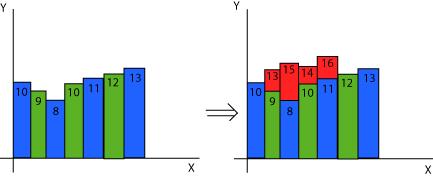
We have a simple algorithm to draw a set of elements in 3D that occlude each other, that algorithm is called painter algorithm. It consists of sorting everything and draw the world from back to front. Each time you draw an element you don't care about what is already on the screen you draw it anyway because you know that the last element is the one on top. One major inconvenient of this algorithm is that it is rather expensive to draw everything even what may be occluded. This phenomenon is called overdraw. The rare occasion where overdraw is good is when you are drawing transparent object in which case this isn't really overdraw because nothing is occluded. Another major inconvenient that makes this impractical in real life (even if overdraw was free) is that the sorting path is not always possible. Most of the time you can't really sort a scene from back to front in a simple way (it might require dividing polygons or elements to sort them out).
We don't want overdraw, in fact we want zero overdraw and only because we can without having to sacrifice anything else. What I call reverse painter is a pun on the previous algorithm, we do everything in reverse. First we draw our elements front to back. Then when touching a pixel, we look first if something has been drawn on this pixel, if this is the case we don't write our color because that means that whatever was drawn first must occlude the new pixel.
Sorting is easy. We have big blocks of data that we can sort between each other because they don't intersect (zones). At the beginning of a frame, I take all potential zones (in a circle around the camera), I put them all in a structure where they are sorted by their distance relative to the camera. Then I take all zones in their order (front to back) and I draw them using four simple cases depending what side of them I see first.
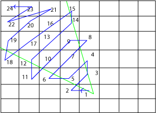
When drawing an individual zone we have to decide on a pattern to traverse the 256x256 rectangle, once again this is trivial, we have four cases :
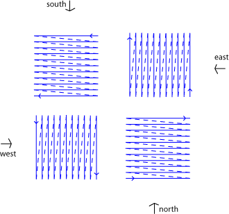
The arrow indicates in which direction the viewer look at the zone. You may wonder how good is this mechanism to sort front to back in 2D when you're going to read a displacement information from a texture and that is going to mess with your good ordering. Actually it won't. Simply because the displacement is in a constant direction, the relative position of each terrain element will stay exactly the same.
If you're familiar with 3D accelerator, then you probably know the Z-buffer algorithm, that allow you to draw your geometry in any order and to let the Z-Buffer sort out the visible pixels from the occluded. This would work of course, but we don't really need that. The thing to remember with a Z buffer is that if you don't sort then there may be situations where you have as much overdraw as the painter algorithm (if by accident everything is drawn back to front). You get limited by the resolution on your Z-data. In some cases drawing two objects near to each other they will overlap themselves badly because we've hit the resolution limit of the Z-Buffer. Also you have to access Z data for each pixel to determine if your new pixel is occluded, you can accelerate that access with a hierarchical Z, but once again you don't need that if you draw everything as we've described here. If you need the Z Data to do some frankenrender (that is combine the output of the voxel engine to use in a more general purpose engine) then you can write the Z Data optimally once per pixel, exactly as you write the color data. But you don't need this Z data to do any occlusion in the voxel engine.
Y-Buffer
How to determine optimally if a pixel has already been drawn ? Generally speaking you would need one bit of data per pixel that is on, if something has been drawn and off else. But we can do better because we draw only vertical and screen aligned blades. The algorithm is called Y buffer as a reference to the more complete Z buffer algorithm. We'll maintain a single line of integer data that will contain for each vertical column of pixel, what y was last written by our engine.
How does that work ? Each blade of terrain, occupy the zone of the screen below its vertical spot, the only condition where this doesn't go all the way down to the bottom of the screen is if it is partially occluded by a previous drawing. That means that when we draw a blade, we get a new Y vertical position on the screen, then compare it to the existing Y for this column, if the previous Y is bigger than the current Y, then we skip the drawing (occluded) else we draw a single color from the current Y to the older Y. This way we draw pixels only once and the occlusion of individual pixels is correct.
Level of detail
Because of the perspective we use, zones that are far away from our point of view will only cover a small zone on the screen. There is no need to go through the pain of evaluating a map of 65536 elements when only one or two pixels might be drawn in the end.
We use a basic LOD system, this is also called MIP mapping (multum in parvo, a lot in little). Instead of considering the whole 256x256, we will grossly estimate how much space this zone will cover horizontally on the screen, then we will get the smaller representation that will roughly be equivalent to one terrain element per pixel (we can go for multiple pixels per elements if we want faster but lower quality rendering). So if the terrain zone covers 16 pixels on the screen we decide we can go for a 16x16 representation. Each NxN representation is a filtered version of the larger 2Nx2N representation.
That means for each terrain zone of 256x256, we have 8 other representations of smaller size, 128x128, 64x64, 32x32, 16x16 etc.
We do that for both height information and color (diffuse) information.
Texture mapping
Usually texture mapping in 3D is tricky because we have to do a perspective correction of UV, filtering and so on. Now we're lucky because our algorithm does handle texture mapping nicely, in fact when we traverse our 256x256 square we do it in texture space and we don't take any shortcut when projecting terrain elements on the screen. For each terrain element we read a single height from our height map and a single diffuse color from our color map and the position on the screen is correct as a part of the projection process.
Summary
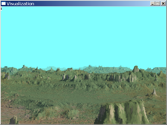
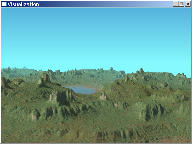
Here's what comes out of our engine so far. We added a bit of aerial perspective (blue coloring in the distance), I'll detail that later. We still have a low quality because I use a LOD selection where one terrain element is roughly covering two pixels horizontally.
Now how can we improve the quality ? First we should have one terrain element covering one pixel or less horizontally (we don't have that fine grain for vertical resolution because it's hard to determine beforehand how it will be expanded on the screen). Then we can use supersampling and use a better sky model, I'll detail those below.
Horizontal supersampling a brute force approach
Doing supersampling is easy. You just need to multiply your rendering definition by two (or four or more). Now that means twice as much memory for the frame buffer, and drawing twice the pixels, twice the bandwidth, etc. You don't need to use a finer LOD selection because in the end, those supersampled pixels will end up as one single pixel on the screen. That means with all things equal that the computing phase before the frame buffer is equivalent to the non supersampled version and only when the frame buffer is accessed do we need to multiply the access. Of course you can use a finer LOD for even more quality but that may not be really needed.
With all other things activated at the highest levels, enabling a four time supersampling (horizontally) means a 50% increase in cycles. We don't have a four time increase luckily because we don't spend 100% of our time drawing pixels and we don't increase other costs.
The resolve path is using a block filter, four samples are added and their color value is divided by four, this is good enough for now. There are better filters that minimize rope effects, while reading more than four samples per pixels, but we don't need that now (you can browse my ray tracing articles for a use of a better antialiasing filter).
Vertical supersampling the fast way
When using a separable filter that means that you can filter along X and Y separately, in fact we'll use two different methods to do the antialiasing along the X axis and Y axis. The X axis was brute force, the Y axis will be a little more efficient.
We abuse the Y buffer algorithm that we've described above. Instead of storing pure integer in the Y buffer we store fractions of pixels instead. So if we touch a pixel we can determine through the fractional Y value how much of the pixel is covered.
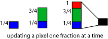
The final pixel will be written only when the four samples (in this case) are covered by taking the mean color value. So this is an incremental resolve behavior, no need to do an extra pass at the end to do the resolve like we did for supersampling above. This is guaranteed to work, because the variation of Y on a single column of pixels is monotonous.
The cost is not much, for 4 vertical samples per pixel and everything else enabled we end up spending 15% more cycles than regular rendering.
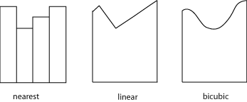
Linear interpolation
We can represent our blades of terrain as single rectangular blocks aligned to the screen space. But in order to get a smooth effect, we need to interpolate between terrain elements. What I used here is a linear interpolation, which gives us a "polygonal" look at a distance. I only interpolate height between two adjacent terrain elements but I could also interpolate diffuse color or other attributes.
Fog and water
In the real world, at a distance everything becomes slightly tainted in blue and desaturated. This is what painters called aerial perspective. This is caused by particles and molecules in the air that affect the color on the way to your eye. If you look at the real picture of Utah on top of the page, you can see that the mountain far from where we stand are really blue looking and it's not their "true" color. This is the same for the sky, it looks blue when we know that the space behind it is really black, the color we see is what is reflected by the air molecules from here to there.
There are several way to implement that in the code, the easiest way, is to take the computed Z, divide it by a max Z value and linearly interpolate between the "real" color of the terrain and a fog color value that is light blue. It is in no way physically correct but that looks well enough for what we want to do and more important it is fast.
We also have some area covered by water. Those are the area that are below a certain level. Water should be reflecting the environment but let's forget about that we'll just make it reflect the sky color and combine it with the part of the terrain that is below water level. If you want to see how to model more interesting water with a refraction and reflection angle go look at my ray tracing articles, everything is explained (Fresnel, Descartes etc.)
Modeling of the sky
Modeling the sky is quite complicated, you have two kinds of scattering (mie and rayleigh), rayleigh scattering diffuses predominantly blue waves in almost every direction, mie scattering sends all waves forward and backward, creating a white halo around the sun whose size is depending on the concentration of particles/molecules in the air. The light going through several layer of scattering becomes tainted by itself, affecting the particles and also lighting the ground directly and through the multiple scattering.
Well in short the sky looks blue, saturated blue as you look up, and more and more unsaturated sometimes white or grayish when you look down near the horizon. It also looks whiter in the direction of the sun.
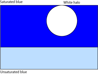
This is for the day and without clouds, because at dawn or dusk, the sunlight has crossed so many layers of air that it has lost most of its blue and starts to taint everything orange or red. During the day the sunlight is almost pure white or light yellow, and what is not in direct sunlight is almost blue because its main source of light comes from the blue sky.
What I did in this program is simply take the saturated blue (1) and unsaturated blue (2) make them blend in a gradient that grows vertically from top to bottom of the screen (the horizon being the blue number 2). The sun is not physically present but I keep track of the sun angle. The saturated blue (1) is blended with more and more white as the angle of view comes near to where the sun should be (Nth power of the cosine the view angle minus the sun angle).
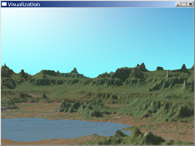
Conclusion and future work
Here's the final output of the program, so we started with a height map and a diffuse map that we cut into small pieces so that we could quickly cull the parts that are non visible. We use a fast occlusion detection that allows us to update a pixel only once and gives us a vertical antialiasing at the same time. The background is a simple procedural model of the sky and sun.
What can we do to improve this engine ?
At this level of quality it is not really fast and almost non interactive (3 fps on my machine in extra high quality, more than 20 fps in the low quality version). There is definitely room for performance improvement, through new and more efficient algorithms, profiling of the code eliminating code pitfalls, and reworking some of the critical paths in assembly (using latest CPU extensions).
Also, the terrain is entirely loaded in memory which is OK for a simple technical demo, but what if we want to represent a real looking world with gigs of data. Then we would have to use the LOD algorithm and push it further so that we would be able to load only the parts that are visible and at the lowest level of detail to reduce the memory footprint.
The lighting and shading is static because it is done during the authoring process by an offline renderer that isn't very fast, even if its results are top quality. We could surrender some of this quality to make an interactive dynamic lighting engine with light conditions updated in real time. We could also implement a more complex model of sky, to be able to get realistic looking sky for various times of the day or seasons, with procedural clouds and so on.
I'll finish that article here, with this list of improvements that could be implemented as an exercise of the reader. I hope to have you interested in digging this kind of engine a bit more.
Source code and executable here : voxelweb.rar (5.77Mb). Download winrar.
More articles and commentaries : Back to journal.